Step 1: Fault motion and focal spheres
During this lab you will determine the focal mechanisms of the August 17, 1999 Turkey earthquake and the December 26, 2004 Sumatra earthquake. First, however, we will review how we can determine the fault mechanism from the first motion direction of far-field P waves.
On the links below, the different types of fault motion are illustrated. Run the animations to see the direction of motion. For the non-vertical faults, the foot wall is the lower block, the hanging wall is the upper block.
Different types of fault motion - animations:
Strike slip: either
right lateral strike slip or
left lateral strike slip
Or a combination, for instance, a
oblique right lateral thrust/reverse fault or a
oblique left lateral normal fault
The direction of P wave displacement in the far field depends on the type of fault motion that causes the earthquake, or in other words, the focal mechanism of the earthquake. For some take-off directions the P wave first motion will be away from the source, this type of motion is called compressional motion. At the recording station the ground will first move upward, therefore a compressional motion results in a upward or positive polarity. In other directions, the P wave particle motion will be towards the source, this type of motion is called dilatational motion. At the surface, the ground will first go downward and therefore, dilatational motion results in downward, or negative, polarity observations.
The polarities can be plotted as a function of take-off angle and propagation direction in a stereographic projection. The figure on the website below shows in what kinds of patterns of P wave first motions the different types of fault motion result. The dark quadrants are directions and take-off angles for which the P wave motion is compressional (upward at the station), the white quadrants represent directions and take-off angles for which the P wave motion is dilatational (downward at the station).
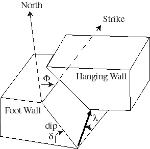
Figure 1. The orientation of a fault plane is given by its strike (measured as an angle clockwise from North; the plane dips towards the right if you look in this direction) and its dip (measured as an angle positive from horizontal). The orientation of the slip vector is given relative to the strike and is called rake (l). When a fault is vertical, the footwall is taken to be the block on the left hand side as you look in the direction of the strike. When l = 0, we have a left-lateral strike slip fault, when l = 180, we have a right-lateral strike slip fault.
After having studied all this, you should be able to answer the following
questions:
1. The parameters that describe the two nodal planes (or possible
fault planes) of an earthquake with their associated slip angles are given by:
F1=318,
d1=88,
l1=178,
and
F2= 48,
d2= 88,
l2= 2,
where F, d, and l denote strike, dip, and rake of the
two fault planes.
Plot the focal mechanism on the stereonet.
(Use a piece of tracing paper, push a push pin through the center of the
stereonet and attach a piece of tracing paper on top of it.
Mark North on the tracing paper.
Plot the two nodal planes.)
What kind of fault motion was it?
2.
Plot for each of the following three cases the focal mechanism.
This means that you have to find the second nodal plane from the strike, dip
and rake of the fault plane.
Also indicate the P and T axes, and describe the type of faulting.
a)
F=280,
d=60,
l=90.
b)
F=140,
d=70,
l=-90.
c)
F=70,
d=80,
l=180.
3.
Briefly describe the tectonic setting of the following three locations:
a) Southern California (Fig. 5.6-14, p.344),
b) Costa Rica (Fig 5.2-4, p. 294), and
c) the East African Rift Zone (Fig. 5.6-2, p.335).
d) Where do you think the earthquake of question 1 occurred? Why?