Lecture Notes of Week 2: Non-Fossil EnergyResources and Utilization of Underground Space
Prof. Dr. C.J. Spiers
1. Introduction
The industrialized world’s number one energy source at present is that of fossil fuels (oil, natural gas and coal). Taking into account global population growth, fuel/energy consumption rates and trends in 3rd World development, society is obviously faced with serious problems regarding fossil fuel supply and use in the coming decades.
The main problems associated with on-going use of fossil fuels are:
- Their non-renewable nature (shortfall in supply vs. demand).
- The environmental impact of combustion (release of greenhouse gas CO2, air pollutants SO2, NOX,heavy metals), extraction (water pollution) and transport (spills).
- The strategic and economic aspects of dependence on supplier nations.
These factors are steadily forcing the industrialized world towards more efficient use of fossil fuels, emissions reductionand cleansing, new exploration and recovery technologies, and of course towards alternative energy resources.
This week, we will briefly look at the role of alternative energy resources, at fossil fuel/energy storage, and at emissions reduction and waste disposal strategies in the global energy picture. It will emerge that significant space will be needed in future for the storage of fuel/energy and disposal of energy production wastes - space that will be at a premium as world population grows and development globalizes! One answer may be to "go underground", i.e. to make use of the Earth's uppermost crust.
We shall examine the accessibility and properties of this region and its potential as an underground space resource. We will focus on the storage of gasses and the disposal of hazardous wastes in geological formations. In addition we will briefly consider ideas on developments in underground transport and urban infrastructure.
1.1. The Changing Global Energy Picture
Until relatively recently, direct economic considerations have determined the choice of energy sources for industrial and societal applications in the industrialized world- with the result that cheap fossil fuels have become overwhelmingly dominant. However, technological advances mean that other types of energy are now becoming economically more competitive. Moreover, the environmental, public health and strategic disadvantages of fossil fuels, as well as protective legislation and looming exhaustion, are now seen to imply longer term costs which neither fossil fuel producers nor users can afford to ignore.
These economic pressures are changing the world's energy picture through the actions of industries and governments. Indeed, market forces are beginning to bring about change. Changes occurring and measures being taken include the following:
- Developments in fossil fuel exploration and extraction technologies.
- Energy conservation through improved efficiency.
- Long term and strategic storage of fossil fuels and derived energy.
- Development of "clean" combustion and emissions storage/immobilization technologies.
- Shift to alternative renewable and inexhaustible energy resources- ultimately no escape from switch to or more widespread use of alternatives!
2. Alternative Energy Resources: What are the Options?
Alternative (non-fossil) energy resources include the following:
| Existing Technologies | Developing Technologies |
| Biomass energy Hydroelectric energy Nuclear energy (fission) | Geothermal energy Solar energy Wind energy Wave energy Tidal energy Nuclear energy (fusion) |
Let's consider these one-by-one and see what conclusions we can draw.
2.1. Biomass energy
This is energy obtained from plant material and animal waste (biomass) by direct burning, by burning the decomposition products (methane) or by burning fermentation products (alcohol).
Directly burnable biomass includes wood, dung, agricultural wastes (e.g. husk, straw), household waste and sawmill waste. Burning of wood and dung supplies about 40% of the energy used in developing countries. In the developed world, electricity produced from biomass accounts for 2-4%. In regions of sugar-caneproduction, incinerating the waste offers major potential for electricity generation; this supplies 30% of Hawaii's energy !
Biogas is the term given to methane produced by the degradation of plant and animal wastes and released frommunicipal refuse (landfill) sites. It is becoming widely utilized on a small scale in developing and developed nations. Alcohol fuel, produced by fermenting grain, is expected to offer a useful additive to petroleum (1:9) as oil reserves dwindle.
The advantage of biomass energy is that it is renewable, provided that the replenishment rate balances the depletion rate. Increased use of biomass is therefore achievable via controlled "farming" operations. In developed environments,burning more household waste offers electricity generation potentialup to 5-10% of national needs. The disadvantage of biomass is that combustion liberates CO2 and ash, as well as a range of carcinogens including dioxines in the case of refuse incineration. This has caused public alarm in Europe in recent years.
2.2. Hydroelectric energy
The gravitational potential energy stored in the water of lakes, rivers and dams provides an emissions-free way of driving turbines to generate electricity, i.e. hydroelectric energy. This presently accounts for about 20% of the world's electricity and 5% of its total energy consumption.
The advantage of hydroelectric power is that it is "clean". Large-scale hydroelectric energy production means building dams and reservoirs. Such facilities are often useful in flood control, for water resource management and for recreation. However, they are expensive, have a limited lifetime (due to silting up), consume agricultural land, damage river systems, change erosion patters, upset river ecologies and even trigger seismicity. In developed countries, the environmental costs outweigh the advantages, except in the case of small scale projects in mountain areas or for aluminium smelting. In developing countries with suitable sites, notably in Asia, the (global) benefits still outweigh local environmental costs (e.g. Three Gorges Dam Project,China). As an ultimate limitation, the planet's total "riverpower" means that hydroelectric energy can never supply morethan about 30% of present global energy needs.
2.3. Nuclear energy
Spontaneous decay of radioactive isotopes is an important source of the Earth's internal heat. Some of these isotopes, notably those of uranium, can become concentrated in the Earth's crust by sedimentary and diagenetic processes to form deposits of dense, radioactive oxide minerals (uraninite, pitchblende). These can be mined and used to produce energy via the process of nuclear fission (nuclear splitting).
Existing nuclear technology relies primarily on fission of 235U. When a sup>235U atom interacts with a low energy neutron (< 10-17 J), it disintegratesto yield two product atoms (e.g. 148La + 85Br),2-3 emitted neutrons and a loss of net mass. This lost mass is converted into a huge amount of energy given by the infamous relationE = mc2. If sufficient 235U atoms are present,the emitted neutrons can give rise to a chain reaction. If this proceeds uncontrolled, a nuclear explosion results - hence the bomb!
In a nuclear reactor, however, fuel rods containing 235U-enriched uranium oxide are typically separated by control rods containing a neutron-absorbing material (e.g. graphite, boron). Reaction progress in this, the reactor core, is controlled by withdrawing or advancing the control rods. The core is cooled by circulating a fluid and the heat energy removed is used to drive steam turbines that in turn generate electricity (Figure 1). Currently, about 16% of the world's electricity is nuclear-derived (~400 235U reactors). In the U.S., the proportion is ~20% rising to over 50% in France and Japan where fossil fuels are scarce.
In the 1950's, nuclear energy was hailed as a clean, cheap solution to global energy problems. Uranium minerals certainly constitute the largest nonrenewable energy source on Earth. Per unit mass, nuclear fission also yields more than 106times more energy than burning carbon. Moreover, during normal operation, nuclear plants release sub-background radioactivity.
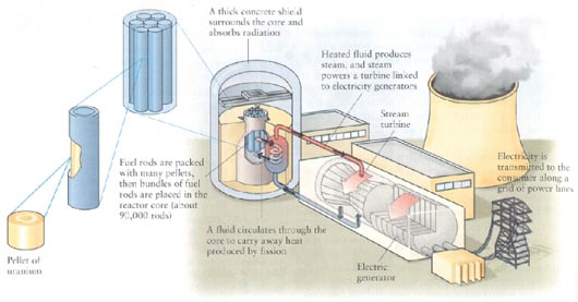
Figure 1. Schematic diagram showing main components of a nuclear power plant
Compared with coal-burning, they also release less radioactivity and carcinogenic matter into the environment per kWhour, they produce vastly less solid waste and NO greenhouse gasses. Sounds great!! However, a variety of disadvantages of nuclear energy have emerged since the 1970's. These are as follows:
- - Uranium mining sites and wastes pose major environmental risks.
- - Power plant accidents can have major impact (Chrenobyl, Three Mile Island, meltdowns).
- - Safe disposal of waste and spent fuel is hard to guarantee onrelevant time scales (< 1 Ma).
- - Plant decommissioning not properly planned/costed.
- - Plutonium production, trade and theft for weapons proliferation.
The impact and true costs of these factors make nuclear energy far less environmentally and economically attractive than originally claimed. Fission energy may have a transient role to play in the fight to reduce CO2 emissions but it offers no long term solution the world's energy needs. Little expansion is likely and Germany recently announced plans to reduce nuclear capacity.
Nuclear fusion, the process that occurs in stars and hydrogen bombs, is an attractive energy prospect which would be virtually inexhaustible and pollution free. However, despite on-going research, building our own "star-in-a-jar" will remain a dream for at least 50 years.
2.4. Geothermal energy
This originates from the Earth's internal radiogenic heat. Average terrestrial heat flow is minute compared with solar input (0.06 vs. 1200 Wm-2), but in certain localities useful amounts of energy may be conveyed to the surface by circulating groundwater or injected water. Recovered water can be used for heating whereas steam can also be used for driving turbines to produce electricity. There are 3 main types of geothermal reserves:
- Geopressurized Reservoirs. These are deep sedimentary basin sequences containing large volumes of high pressure pore water, warmed by normal heat flow. Such water can be extracted and the heat used. The Paris Basin Project heats some 20000 homes in this way.
- Hydrothermal Reservoirs. These are systems of hot water and/or steam circulating in porous or fractured rock (Figure 2). For practical electricity generation, geothermal steam must exceed 180oC and must be located at depths < 3 km. Most useful hydrothermal deposits are thus limited to volcanically active plate margins and hotspots where the geothermal gradient is steep. Examples are located in N. California, Japan, New Zealand and Iceland.
- Hot dry rock. In areas with an above-average geothermal gradient, the energy stored in hot, dry, volcanic or crystalline rocks can potentially be recovered by artificially fracturing the rock and then pumping water through to produce steam (Figure 3). Fracturing at suitable depths (5-7 km) can be achieved using explosives or high-pressure water, but much R&D is needed to achieve uniform fracturing, water migration and heat transfer.
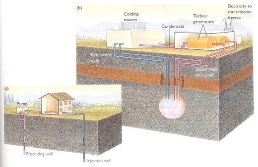
Figure 2. Hydrothermal reservoirs in areas with a high geothermal gradient. a) Shallow, low temperature system for domestic heating. b) Generation of electricity using deep-seated, high temperature steam (>180oC) to drive turbines. Condensed water is reinjected.
Geothermal energy has the advantages of low impact, continuous availability and easy location. However, deep drilling and steam transport are costly, and if energy extraction rates exceed natural supply, field lifetimes may be only 20-30 years (effectively nonrenewable). Geothermal fluid extraction can also lead to subsidence and surface water contamination. Unfortunately, geothermal potential can probably supply only 5% of human needs. Nonetheless, it will remain an important and economic resource in volcanic localities.
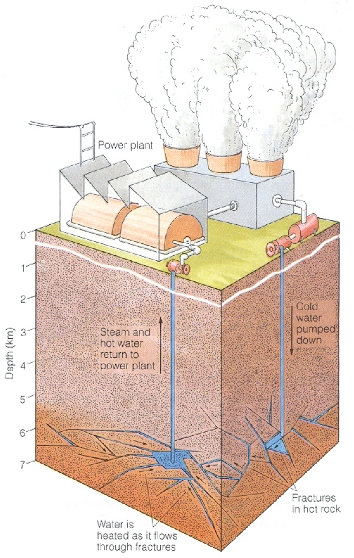
Figure 3. Geothermal energy extraction from hot, dry, crystalline rock at depth (5-7 km). Cold water is pumped through induced fractures at the well-bottom and steam is retrieved and used to generate electricity via turbines.
2.5. Solar energy
The energy reaching Earth from the Sun is (4x1024J/year - 104 times human consumption! It is clean and "free". However, it arrives in very dilute form and is unevenly distributed both spatially and temporally, depending on latitude and cloud cover. The challenge in utilizing solar energy thus lies in how to collect and store it. Broadly, there are 4 methods:
- Solar Heating. Solar energy is well suited to heating buildings and domestic water. The principal of the greenhouse can be used to heat homes (passive solar heating). Alternatively, air or water can be pumped through rooftop collector panels, and used to supply/store heat and hot water (active solar heating). It's catching on where economic!
- Solar-Thermal Plants. Here, the Sun's rays are concentrated using reflectors to generate steam or other vapour. This is used to drive turbines and generate electricity (Luz, USA - see Figure 4a).
- Solar Cells. Solar energy can be directly converted into electricity using photovoltaic cells. These consist of credit-card sized, silicon wafer p-n junctions. Photons interacting with the junction create electron-hole pairs, which dissociate in the electric field present there, into the n and p regions respectively. This generates a potential difference of up to 0.5 volts, which can supply ~0.6 W of power with an efficiency of up to 15%. Solar cells must accordingly be coupled in large arrays to be useful for high-power applications (Figure 4b).
- Solar Hydrogen Fuel. This somewhat futuristic notion involves using solar electricity to electrolyze water thereby producing hydrogen. The energy is thus stored and can be usedat will as a clean, combustible, fossil-fuel substitute.
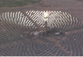
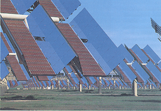
Figure 4. Two methods of collecting solar energy. top) Solar-thermal plant. bottom) Solar cells.
The obvious advantages of solar energy are that it is inexhaustible, free of direct raw material costs and virtually impact free. Solar heating and solar cell technology can be implemented on a small local scale needing no infrastructure,and are thus well suited for rural and developing communities. Disadvantages include latitude and weather dependence, as well as space (array) requirements for major power generation. Solar cells are not yet cost-effective and manufacture generates toxic metals waste. Moreover, existing electrical equipment is not suited to solar electricity supplies. Nonetheless, market forces are promoting on-going R&D in solar electric technology and if present trends continue, solar energy could supply 20-30% of the world's electricity by 2050.
2.6. Wind energy
Uneven solar heating of the Earth generates winds, which have long been used to drive windmills. At present,wind energy is mostly used to generate electricity via wind turbines- the modern windmill! Worldwide, around 25 000 installations generate some 3 GW of electric power at a cost which is becoming competitive with coal-based generation (Figure 5). The main advantage is the low environmental impact. However, windmill farms consume large spaces, pose a risk to bird life, generate considerable noise and pose an eyesore, so that public acceptance of large-scale use is questionable. Most importantly, wind power requires consistent wind speeds (> 20 km/hr). Suitable surface winds are only locally available and can provide only ~10% of present energy usage. Wind energy may therefore be locally important (e.g. Denmark, Netherlands,windpumps in developing countries), but not globally.
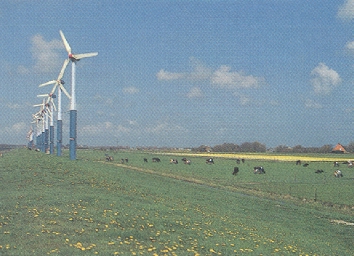
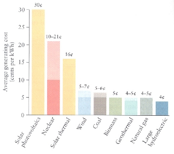
Figure 5. top) A wind farm here in The Netherlands. bottom) Present cost of generating electricity using different technologies. Note that wind energy ranks similar to coal-derived energy.
2.7. Wave and tidal energy
Marine waves, created by wind, carry huge energy but a means to harness it on a useful scale have not yet been found. Most research concentrates on using wave kinetic energy to move floats or to compress air and thus drive turbines. A major problem is corrosion by seawater.
Tidal forces, originating from the gravitational attraction of the Moon and Sun for the oceans, offer a means of trapping (damming) seawater at high tide and releasing its potential energy at low tide to generate "hydroelectric" power. Tidal energy is inexhaustible, fuel-free and non-polluting. There are numerous marine inlets around the world with sufficient tidal range to be usefully dammed. However, the effects on sedimentation and finely balanced coastal ecology are hard to predict. As for wave energy, tidal generation sites are inevitably localized to coast lines. In addition to the energy transport problem, the periodic nature of tidal generation requires some kind of storage capacity. At present, plants are operating in France, China, and Russia, but the potential of tidal energy for the future is unclear.
2.8. Conclusions
The world cannot continue indefinitely to use fossil fuels because they are inefficient, nonrenewable and because of emissions of pollutants and CO2 greenhouse gas. The developed world's population and energy demand is reasonably stable. However, developing countries are likely to drastically increase their demand for energy in the coming 20-30 years. Interim measures include improved fossil efficiency, strategic storage, and reduced emissions.
However, integrated market forces will ultimately force a shift to non-fossil alternatives. Both interim and long-term measures must be promoted in developing countries. Nonetheless, the evolution of energy production is going to vary strongly from region to region, driven by local potential and economics. Decentralized renewable sources (solar, biomass, hydroelectric, geothermal) will play an important role in rural areas of developing countries. Developed nations with an energy distribution infrastructure and major needs will first improve use of fossil fuel. In the next 50 years, some may expand nuclear energy (if the disposal problemis solved) and store CO2 underground to reduce emissions. Where locally economic, they will implement wind energy, hydroelectric,geothermal and possibly wave power. In the longer term, unless fusion becomes a reality, there will be little choice but to use solar power, achieving the necessary storage and transport capacity by converting into hydrogen fuel.
3. Utilization of Underground Space
The World's changing energy and global environmental picture means that major space resources will be needed in future for a variety of purposes. These include long-term and strategicstorage of oil and gas, storage of energy derived from fluctuating sources (solar, wind, tidal), and disposal of energy-related wastes such as radioactive waste and CO2 as well as other industrial and municipal wastes. As population grows, however, surface space will have to be conserved for agriculture, water resources, forestry and energy production (e.g. solar). Underground space, i.e. space existing or created in the upper crust, offers a possible solution. In addition, the subsurface offers attractive possibilities for accommodating future urban infrastructure and transport systems. Some typical examples of underground space utilization are given in Figure 6. We will now consider some of these.
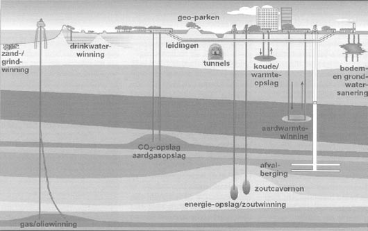
Figure 6. Typical examples of undergroundspace utilization, as envisaged by the Netherlands Institute of Applied Geosciences (NITG-TNO) in Utrecht. Note the gas/oil production from deep reservoirs (Dutch: gas/olie winning), energy storage in solution-mined cavities (zout cavernen) in salt domes (energie opslag / zout winning), waste disposal in clay formations (afvalberging), CO2 disposal and/or natural gas storage in reservoirs and aquifers (CO2 / aardgas-opslag), geothermal energy extraction (aardwarmtewinning), cold/hot water storage (koud / warm water opslag), and underground infrastructure.
3.1. Going Underground: The Accessible Region and Favourable Host Rocks
In considering underground space utilization, the first questions arising are:
- What depths can we access in practice?
- What host rocks are best suited to our needs?
Civil and geotechnical engineers have extensive experience in constructing buildings, tunnels, and waste disposal sites (landfills) in the shallow subsurface (0-50 m). Conventional mining is possible to depths of 1.0-1.5 km, so that tunnels, galleries and rooms can also be constructed to these depths in suitable rock. At greater depths, temperatures and rock (overburden) pressures become too high, leading to unworkable conditions (T > 37oC) and widespread roof instability. The oil industry, however, routinely drills to depths of 3 km and frequently nowadays to 5 km (T <180oC), meaning that fluids can easily be injected into rock at these depths. Deep drilling research projects have achieved depths up to 9-10 km (e.g. KTB Borehole, Germany) but progress beyond 5-6 km is fraught with difficulties.
The principal requirement for deep underground (geological) storage of fuels or hazardous wastes is isolation (sealing) from the groundwater system and hence from transport into the biosphere and atmosphere. Underground infrastructure must similarly be sealed against inundation by groundwater. In broad terms, then, the most suitable host rocks are those with low porosity and permeability, or porous reservoir formations sealed externally by impermeable strata or faults.
However, aside from the initial rock properties, any human interference (mining, disposal, fluid injection) with a particular geological formation will tend to disturb the entire local geological-hydrological system from the steady conditions reached over geological time. A crucial question in evaluating the performance and safety of any deep underground operation is how will the host rock and surrounding geological environment respond. The main factors affected are:
- stress field (i.e. the field of forces transmitted through the affected rock mass)
- temperature field (spatial distribution of temperature)
- deformation field (spatial distribution of distortions)
- (geo)chemical equilibrium/state
- rock properties (e.g. porosity, permeability)
- groundwater flow field
To address how these coupled factors will evolve and how the site will behave requires input from many branches of Earth sciences - geological and geophysical surveying, rock mechanics, rock physics, geophysical modelling, geochemistry and hydrology. In general terms, the following offer promising properties as host rocks for underground space utilization.
3.1.1. Clay-rich Rocks. Clays, mudstones and shales usually have very low permeability and thus good sealing potential. Moreover, clay minerals can retard or prevent the migration of a wide range of inorganic and organic substances via ion-exchange and surface adsorption processes, forming a natural chemical barrier. Clay-rich rocks are also common and tend to flow plastically (i.e. like plasticine) rather than fracture under load (stress), thus retaining their sealing potential. However, they do not respond well to exposure to dry air, especially if heated; this leads to dehydration, embrittlement and porosity development.
3.1.2. Crystalline Rocks. Intrusive igneous masses such as granitic plutons are also characterized by very low rock permeabilities when unfractured. Such bodies are common and have huge volume. Their constituent rocks are mechanically strong and resistant to moderate temperature changes. Such rock is rather brittle, however, and care must be taken to avoid fractured regions or induced fracturing.
3.1.3. Rocksalt (NaCl Rock). This is an attractive medium for underground space use and is already widely utilized. Rocksalt deposits form in restricted marine basins, such as arid rift environments, when the sea-water evaporation rate exceeds the supply of fresh water (e.g. present day Red Sea) - see Figure 7. They are very commonin the geological record and are often very thick.
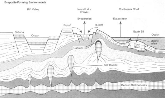
Figure 7. Schematic illustration of theformation of rocksalt by sea-water evaporation in restricted marine environments. Note also the salt tectonic features (salt domes or diapirs) developed as a result of the mobility and low density of (ancient) rocksalt layers buried deep in the geological succession.
Rocksalt possesses extraordinary properties which are responsible for a wide range of important geological processes. First, it is a coarsely crystalline rock with extremely low porosity and permeability. It flows plastically under upper crustal conditions with little or no fracturing. Fractures that do form tend to self-heal. It thus has excellent sealing properties as evidenced by the fact that it "caps" many of the worlds largest oil and gas accumulations. It has unusually high thermal conductivity and heat capacity, and low density. During burial under thick sedimentary sequences, rocksalt is so mobile through plastic flow that it gets squeezed around by uneven loading. Since it is less dense than most sediments at depths > 1 km,deeply buried salt also tends to rise upwards under gravity.
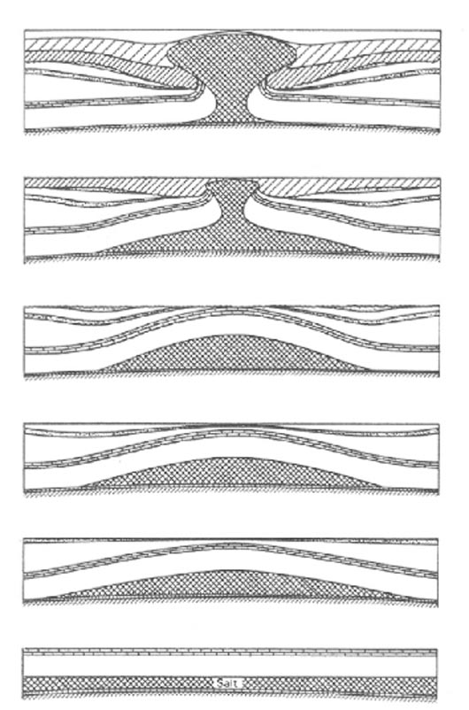
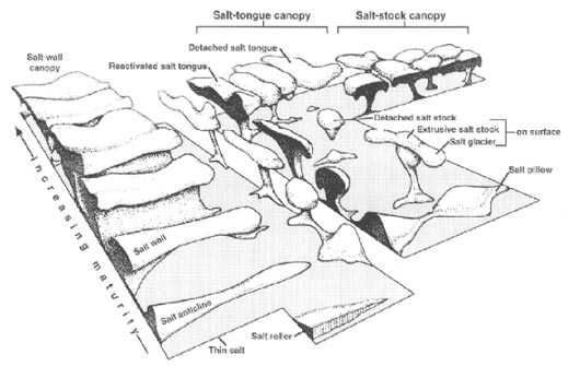
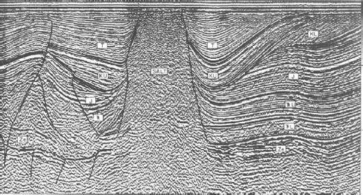
Figure 8. Illustration of salt tectonic features formed as a result of the low resistance of salt to plastic flow, and its low density (buouyancy) compared with other crustal rocks. top) Diapirism or dome formation, as a result of gravitational instability. center) The full spectrum of salt structures formed in salt provinces such as the Gulf of Mexico or N. European Zechstein Basin. bottom) Seismic section showing N.Sea salt dome and associated structures; these form traps for oil and gas.
This whole process of salt movement or "salt tectonics" leads to the formation of salt pillows, domes, and intrusive/extrusive sheets from the original sedimentary layers (see Figures 7, 8). These structures are large and highly suitable as an underground space resource when stable (no tectonism or surface sedimentation). Significantly, salt can be easily mined, notably by solution mining (Figure 9), so large cavities can be easily created. Indeed, solution mining is a major method of salt production in many countries (including The Netherlands), and many (brine-filled) cavities already exist. In some situations,the solubility of rocksalt in groundwater is an obvious disadvantage, as is its mobility. However, many subsurface salt structures have remained both stable and undissolved by groundwater (due to the formation of a "caprock" of insoluble residue coating the surfaces exposed to groundwater) for tens or even hundreds of millions of years, demonstrating the time scale on which they can be safely utilized. Examples of salt provinces where numerous structures are developed include the Zechstein (Permian) of NW Europe and the US Gulf Coast and East Texas Basin Provinces. In all of these, salt structures play a major role in trapping hydrocarbons (Figure 8).
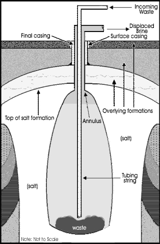
Figure 9. Solution mined cavity in rocksalt. AKZO-NOBEL constructs many such cavities here in The Netherlands for the production of table/cooking salt. Such cavities offer enormous capacity for underground storage of oil or natural gas.
3.1.4. Porous Reservoir Rocks. Porous sandstone, volcano-clastic and carbonate formations, sealed from their surroundings by impermeable sediments (e.g.clays, shales, rocksalt) or sealed faults, also offer attractive sites for the storage and disposal of injected gasses and liquids (Figure 10). Exhausted oil and gas reservoir formations are particularly suitable because they are already known to be sealed, though depletion and re-injection may lead to changes in the stress and deformation fields which could result in leaks. Saline aquifers also offer suitable sites if good seal potential can be demonstrated. Huge volumes are available in the pore spaces of such reservoir rocks, but reservoir compaction and dilation due to changes in pore fluid pressure can often produce significant surface deformation and even induced seismicity.
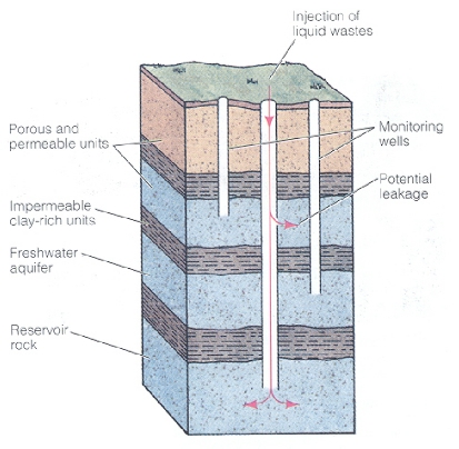
Figure 10. Deep-well disposal of hazardous liquid waste by injection into a hydrologically isolated porous rock unit.
3.2. Geological Storage of Energy
As hydrocarbons reserves shrink, many nations and energy multinationals are developing facilities and plans to store both crude oil and natural gas underground. The motivation for this is partly conservation for future use and partly to reduce dependence on politically unstable or potentially hostile supplier nations. Storage methods considered include re-filling exhausted/depleted on-shore reservoirs to their original pore pressures, injection into saline aquifers and storage in solution-mined cavities in salt deposits. Numerous such operations are already successfully in progress. The principle environmental risks are the possibility of leaks (groundwater contamination) and effects such as surface deformation and induced seismicity. Research is in progress to evaluate these further.
Aside from storing oil and gas, there is considerable interest in storing electrical energy derived from both conventional and weather-dependent sources (solar, wind, tidal, wave) in order to buffer fluctuations in electricity supply and to lower costs. Most designs are based on the notion of underground hydroelectric or compressed air storage systems sited in salt domes or crystalline rocks (Figure 11). Several such plants already operate successfully.
Heat energy can also be stored in and even transported through underground formations by pumping hot water into isolated aquifers, recovering the water at off-peak periods - a kind of do-it-yourself geothermal reservoir. Such schemes are becoming increasingly widespread in Europe and the U.S.A. but are usually aimed at the shallow subsurface.
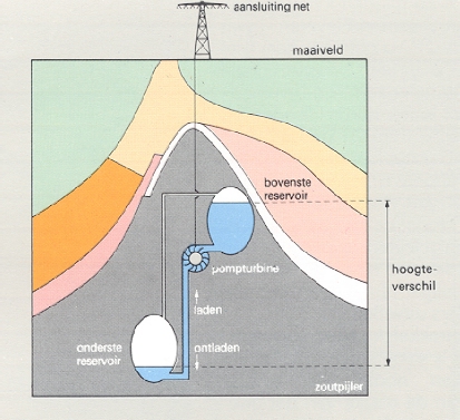

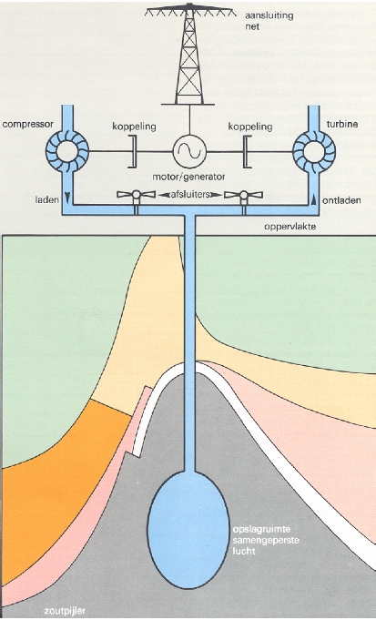
Figure 11. Schematic diagrams illustrating energy storage in solution mined cavities in salt domes. top) Hydroelectricstorage system. center) 3-D geological section of same. bottom) Compressedair energy storage system.
3.3. Underground Disposal of Gaseous and Liquid Wastes
Another use for exhausted/depleted hydrocarbons reservoirs, deep saline aquifers and solution-mined cavities in salt deposits is for the permanent or temporary disposal of gaseous and liquid wastes produced by the energy and other industries. Typical wastes that might be disposed of in this way (i.e. by pumping into the chosen site) include brines and CO2 produced during hydrocarbons extraction, contaminated water pumped from mines and mine waste sites, and liquid chemical wastes. The volumes of such fluids are often so large, that deep geological disposal is more or less the only option.
In the case of oil- or gas-field brine and CO2 disposal in depleted reservoirs or saline aquifers, environmental risks are low because natural fluids are being returned to the geological environment. The practice is widespread, successful and indeed indispensable to the hydrocarbons industry, which has to dispose of billions of liters of reservoir brines and CO2 per day. Separation of CO2 from natural gas at the production well-head and disposal in an exhausted reservoir or aquifer is now becoming important in the fight against the greenhouse effect. Several trial schemes are in progress (Figure 12, see also NITG website). Environmental effects that can occur include leakage into the surroundings and possible groundwater chemistry effects, surface uplift and induced seismicity. Chemical disequilibrium between host rocks or seals and injected CO2 may increase leak potential.
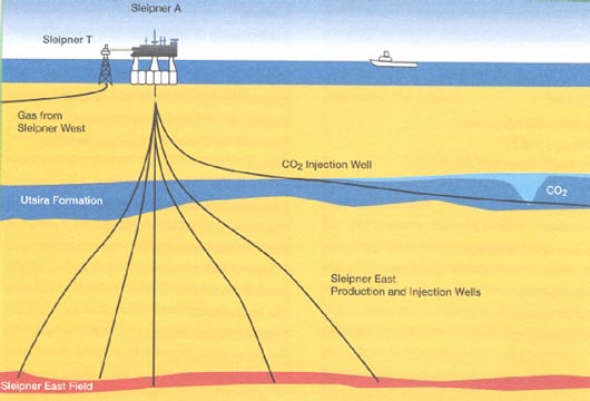
Figure 12. Disposal of CO2 in a saline aquifer, after separation during production from a natural gas reservoir. This is a pilot scheme already in operation in the North Sea to investigate the potential of the method for reducingCO2 emissions during gas extraction.
Injection of toxic fluid wastes into depleted reservoirs or deep saline aquifers is a more risky matter, particularly in view of the long-lived or permanent toxicity of many such wastes. In the past, such operations were carried out with insufficient consideration for the suitability and long term integrity of the host rocks used, resulting in leaks and induced seismicity. However, provided that lined (sealed) wells are used, that a high degree of isolation of the host formation is established (as in a depleted gas reservoir, for example), that the formation is sufficiently deep (> 700m or well below fresh groundwater flow routes) and that the site is monitored for leakage, this method of disposal may be acceptable. It is widely used in some countries, as is injection into solution-mined cavities in rocksalt masses.
The latter method involves injecting fluid at a pressure just below the rock pressure at the top of the solution mined salt cavern. This minimizes the difference in rock and fluid pressure over the entire height of the cavern and accordingly minimizes the rate of cavern convergence via creep of the rocksalt. Nonetheless, the cavern will slowly converge from the base, pushing the fluid pressure up in the long term. When this reaches the rock pressure at the cavern roof, the roof may tend to leak with convergence squeezing the fluid slowly out. On the other hand, field evidence indicates that risks are small. Research is in progress to examine whether caverns can be safely sealed and abandoned or must be monitored. Similar arguments apply for hydrocarbons storage in salt, though such sites would generally be monitored continuously.
3.3.1. CO2 Emissions Reduction through Geological Disposal/Storage
In recent years, geological disposal of CO2 released by combustion of fossil fuels for electricity generation has received growing attention as a means of drastically reducing CO2 emissions and moderating the greenhouse effect. This possibility is essentially seen as a stop-gap measure until increased combustion efficiency and alternative energy sourcesbring down CO2 emissions to acceptable levels within a sustainable energy policy. In the agreements of Rio de Janeiro and Kyoto, a range of nations (including the Netherlands) committed themselves to reducing CO2 emissions by prescribed amounts by 2010 (typically 5-10%). However, it is unlikely that these targets will be met unless underground disposal is implemented. Indeed, CO2 storage/disposal may become one of the most important uses of underground space in the next 50 years. Present operations disposing of CO2 separated from natural gas at well-heads form important pilot projects.
The process of CO2 sequestration, as it is called, involves the following steps:
- Capture at fossil fuel powerstations and industrial plants (e.g. steel plants)
- Compression to pressures > 80 bar (8 MPa) and pipeline transport to the sequestration site
- Injection into a depleted hydrocarbon reservoir or deep salineaquifer (off- or on-shore), or injection into hydrocarbon reservoirs for simultaneous well stimulation or subsidence recovery purposes
Costs are expected to lie typically in therange of 10 - 30 US$ per tonne of stored CO2, and will in many cases be economically feasible, increasing electricity costs by perhaps 10-30%. Estimates for the Netherlands indicate that the total suitable reservoir/aquifer volume available underground is sufficient to accommodate 50-100 times present yearly CO2 emissions. The technology could potentially be used in conjunction with hydrogen fuel production from fossil fuels plus water.
Possible environmental impacts of large-scale underground CO2 disposal/storage include leakage into the hydrological and groundwater system, associated changes in groundwater pH and chemistry, surface uplift and induced seismicity. However, experience with natural gas reservoirs indicates that the risks are low. Further research is needed in areas such as the chemical and physical effects of CO2 injection on long term reservoir and seal behaviour, on monitoring the deep migration of CO2 using seismic techniques and on hydrological impact. This, and the location and verification of suitable sites, will form an important area of interdisciplinary research for Earth Scientists in the coming decades. It is receiving considerable attention within Utrecht University (Earth Sciences, Geographical Sciences, Chemistry, Utrecht Center for Energy Research) and the National Institute for Applied Geosciences NITG-TNO. Look out for internships in this area!
3.3.2. Geological Disposal of Radioactive Wastes
Background. Radioactive waste or "radwaste" is produced primarily by the nuclear power industry, though significant amounts are also produced by nuclear weapons production and decommissioning, and by scientific and medical laboratory activities. Radioactive wastes are classified as low level (LLW), intermediate level (ILW) and high level wastes (HLW), depending on the amount and type of radioactivity emitted, and on how long the hazard persists. Hazard duration depends on the half-lives of the elements presentand in the case of HLW may be up to 105 years. The hazards posed are as follows:
- Exposure to alpha, beta and gamma rays, or to neutrons, emitted directly from the waste
- Exposure via uptake of radioactive material into the body via contamination of air, water or foodstuffs, or via physical contamination
- Extreme toxicity of certain exotic elements, such as plutonium.
Under conditions of normal plant/lab operation and properly imposed safety regulations, the various sources of radiation related to human activity fall well below natural background levels. However, abnormal exposure or releases of concentrated radioactive material into the environment are highly dangerous, as demonstrated by the Chernobyl accident.
Low level wastes include materials such as lightly contaminated protective clothing, syringes, air- and fluid-filters, and medical treatments waste. Such materials are generally sealed in metal drums, which reduces the direct radiation risk to negligible levels. Such drums are often stored on site or are buried in landfills or mines. A major problem is that nobody wants the stuff (the"Not In My Back Yard" or "NIMBY"syndrome),so that storage is often forced to be on-site, regardless of true safety. Intermediate level wastes are too dangerous to be handled as LLW, and are usually separated into their LLW and HLW components, or are stored until they degrade to LLW.
High level waste comes mainly from spent (exhausted) fuel with minor amounts from weapons sources. Spent fuel consists of fuel rods in which the decay process has proceeded to the point where the nuclear chain reaction has become too inefficient to use. Such rods are removed from the reactor core and stored temporarily (under water, for shielding) before reprocessing in order to recycle the fissionable material (235U). The remaining HLW is in liquid form, it is highly radioactive, heat-emitting, and contains a cocktail of numerous daughter elements and radioactive isotopes including 239Pu (half-life 24 000 years) and 90Sr (easily taken up into bone tissue). This hot liquid waste is stored (temporarily) in on-site tanks. The preferred treatment is to then convert it into a solid waste form (borosilicate glass boules) which can then be sealed in corrosion-resistant steel or titanium canisters with various amounts of lead shielding. These containers can also be stored on-site or disposed of in deep geological formations. An additional option is to directly store or dispose of the metal-clad oxide fuel rods. In either case, geological storage or disposal of the solid waste is undoubtedy safer than surface storage of the liquid form. Note that solid waste canisters and fuel rods not only emit high levels of gamma radiation, but they are also hot, with long term temperatures of typically 150 oC. These wastes must be isolated from the environment for at least 104 or 105 years.
Disposal Underground.Most safety analyses have shown that deep underground or geological disposal offers the highest degree of safety for both LLW and HLW. Shallow pit or landfill disposal of LLW is widely implemented and accepted. However, since permanent, 100%-isolation is impossible to guarantee, the NIMBY effect on public opinion has meant that deep underground disposal of solid HLW is a problematic issue. In Europe, most HLW thus remains stored on-site at surface nuclear facilities in liquid form - which many analyses indicate is probably one of the least safe options. Similarly, in the U.S., sites remote from habitation have become the only politically feasible options for underground HLW disposal.
Nonetheless, most "nuclear" nations are keeping the option of geological disposal of HLW open for the longer term. One reason for this is that even if nuclear energy is abandoned, a safe, long-term solution has to be found for the large amounts of HLW that already exist. Secondly, if nuclear energy production has to be expanded temporarily in the next 50 years or so to reduce fossil fuel use and associated CO2 emissions, the problem of HLW will be a bigger one than we already have, both safety- and volume-wise.
Most Earth scientists agree that the ideal geological site for radioactive waste disposal should posses the following characteristics:
- It should be land-based.
- The host rock should have low permeability and should be "dry".
- It should have high thermal conductivity and heat capacity to minimize thermal expansion/stressing.
- Chemical retardation and self-healing properties are advantageous.
- Groundwater flow should be slow and directed away from the biosphere or regions accessible to humans.
- Site rainfall and erosion rates should be low.
- Earthquake and volcanic risks should be very low.
- Future climate changes should be unlikely to affect the hydrological regime significantly.
The most appropriate host rocks are accordingly clays/shales, rocksalt, volcanic tuffs and crystalline rocks.
Clays are under consideration for HLW disposal in most W. European countries, the main advantages being low permeability, chemical barrier function and available volume. In Belgium an experimental facility (disposal mine) has been constructed in the Boom Clay formation. The NIMBY syndrome has led the U.K. nuclear authorities (NIREX) to research disposal of radioactive waste in clay-rich rocks sited directly beneath the Sellafield nuclear plant.
Rocksalt has been considered by numerous countries including the U.S., Canada, the Netherlands, Germany, Spain, and France. Most HLW disposal concepts are based on the notion of a conventionally mined repository, sited in a deep salt layer, pillow or dome (Figure 13). Some concepts focus on permanent disposal, some allow for (temporary) wasteform retrievability. In the case of permanent disposal, galleries and shafts would be backfilled with crushed salt, which would become compacted to the virgin, low porosity/permeability state of intact saltrock by creep convergence of the openings. Detailed numerical modelling studies show that the local heating effect of HLW disposed of in this way would cause only elastic and plastic flow of the surrounding salt, with no fracturing, so that a high degree of isolation is achieved. This has been confirmed by studies at various underground laboratories sited in salt, such as the Asse Mine at Remlingen in Germany.
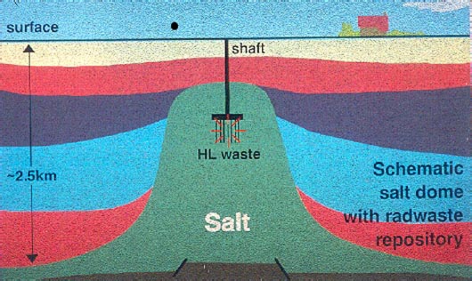
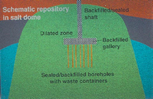
Figure 13. Schematic illustrations of a (top) high level radioactive waste repository constructed in a salt dome using conventional mining, drilling and backfilling techniques. (bottom) Enlargement of the zone of the mine itself
A number of questions remain controversial, however. For example, some physiscists claim that the effects of radiation on rocksalt might threaten containment (nice term project here!!). At present, only two rocksalt repository facilities have been constructed and made operational for HLW disposal. These are the sites at the Gorleben salt dome in Germany (a site for the disposal of power station waste) and the weapons waste disposal facility or Waste Isolation Pilot Plant located in the bedded Salado salt deposits of New Mexico. Public pressure and the NIMBY syndrome have strongly inhibited implementation of the salt option in the U.S. and northern Europe.
Since welded volcanic tuffs (thermally welded ash deposits) have an extremely low permeability, these have also been considered by various countries as possible hostrocks for HLW disposal. In the U.S., public objection to disposal of HLW in populated areas has turned attention towards remote locations, such as deserts. Taking this into account, the site now considered most suitable by many scientists in the U.S., for geological disposal of the national total of roughly 70 kilotonnes of HLW presently stored at the surface, is that at Yucca Mountain in the Nevada desert.
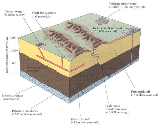
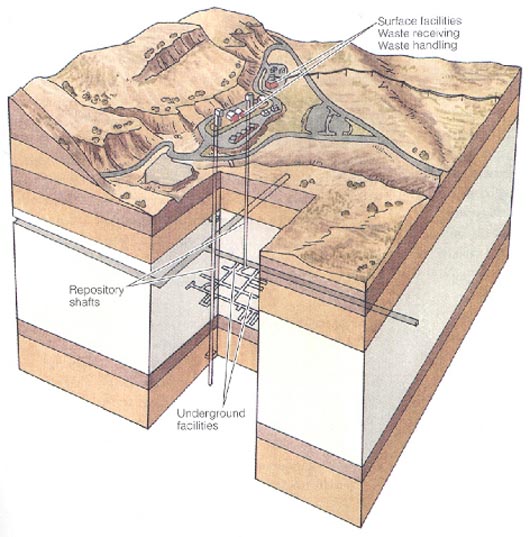
Figure 14. Proposed HLW repository site at Yucca Mountain, in the Nevada desert, US. top Subsurface geology and timing of important geological events. bottom The repository concept.
There, a near horizontally bedded, low-permeability tuff formation (Paintbrush Tuff), extending from the surface to a depth of about 500 m, offers the possibility to construct a mined repository at a depth of about 300 m (Figure 14). The tuff is located some 250 m above the water table and is therefore dry. It also contains zeolites, which can absorb a wide range of ions, should a leak occur. The tuffs were ejected some 8 million years ago from a now extinct volcanic center. They are cut by several minor volcanic pipes and by a large normal fault. However, radiometric and stratigraphic (relative) dating methods have shown that there has been no volcanism or fault motion in the last 10 000 to 20000 years, and the probability of such events in the coming 10000 years is considered low. Nonetheless, this question remains controversial, as does the question of the impact of possible climatic change on the water table and on erosion. Site assessment is likely to be completed by 2002 at a total cost of around $7billion.
Crystalline rock masses such as granitic plutons or ancient metamorphic shield complexes have also been considered by a number of countries as potential sites for locating mined repositories for the permanent disposal of HLW. These nations include France, Sweden, Switzerland, the U.K., the U.S., Canada, and Japan. Japan has also looked at thick basaltic lava sequences. Crystalline rock units, notably in the ancient shield areas, have often been tectonically and hydrologically stable for hundreds of millions of years. Crystalline rocks have very low permeability and are mechanically strong. Their disadvantage is their brittle nature and the difficulty of locating large-scale fracture networks not visible at the surface. At present, Canada is pursuing the crystalline option, principally because it has large expanses of remote shield terrain with little or no population. A major underground (granite) research facility is in operation at Lac de Bonnet in Manitoba.
3.3.3. Disposal of other Solid Wastes
A number of other solid wastes are sometimes, or may in future, be disposed of in geological formations. A notable example is the crushed or granular rock waste produced by mining and mineral processing operations. Such wastes are increasingly being disposed of by returning them to the source mine as backfill, particularly when the waste contains toxic heavy metals or salts. Fly ash, the solid waste produced by coal combustion in power stations and other industrial processes, is also a candidate for underground disposal when concentrations of toxic metals are high. So are the products of flue-gas desulfurization plants, when highly contaminated. Porous pellets of such materials can potentially be disposed of in solution mined cavities in rocksalt, though careful consideration must be given to the possibility that contaminated fluid may be expelled in the long term, as a result of cavity closure by creep of the salt.
3.3.4. Underground Infrastructure and Urban Development
As (con)urban populations and activities expand in the coming decades, pressure on the use of surface space and surface transport infrastructure will inevitably grow. In developed countries, this pressure is likely to come largely from increased economic activity, increased demand for mobility, and increased standards of environmental protection and quality. In developing countries, the pressure is likely to come initially from growth in urban populations and economies.
Against this background, shallow underground space utilization (to depths of up to 50 or even 100 m) will become an increasingly competitive alternative economically, compared with surface space. How and to what extent underground space will be used will vary strongly from city to city and country to country, depending on local economic conditions and environmental quality requirements. Some likely sub-city developments in the coming 30 years include the following:
- Storage and automated vehicular transport of goods
- Storage and pipeline/network transport of fuels and fluid consumables
- Wholesale and mail distribution networks
- Cable and communications networks
- High speed passenger transport systems (automated) coupled with underground parking terminals at city margins
- Underground factories and laboratories
- Sewage treatment plants
- Large scale shopping, musical, dancing and sports venues
Likely underground developments in densely populated residential areas, areas of natural beauty, or ecologically sensitive areas include:
- High speed road and rail tunnels (with increasingly automated passenger + goods transport systems)
- Cable, pipeline and communications networks
- International transport corridors
While many countries, including The Netherlands are actively considering these options and planning their strategies for the future, perhaps the most advanced in its thinking is the country feeling the greatest pressure - Japan! One Japanese scheme is the Urban Geo-grid Plan, conceived by the Shimizu Corporation, as a possible solution to the surface space problems plaguing the choked cities of Tokyo and Osaka. This scheme proposes a 10 km x 10 km orthogonal underground network of transport/communications tunnels connecting nodal grid stations with a 2 km spacing . The grid stations would extend from 25 m to 75 m depth, housing 8-10 stories of business offices, shopping centers, sports facilities and so on. To stimulate use of underground space at depths beyond normal engineering range (>40-50 m), the suggestion is to make this space available for free!